Connecting an Analog Door Box to a 2PGDAD Module
Preparing the 2PGDAD Module
- Following the instructions in your system's Hardware Manual, remove the 2PGDAD module cover and cable knockout.
- Do not connect the 2PGDAD to a 16ESIU port. This will come later.
Wiring the Connecting Blocks
- Position the 2PGDAD Module so the cable knockout is facing towards you.
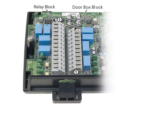
- The 2PGDAD Module has two connecting blocks just above the cable
knockout.
- The block on the right is the Door Box Block.
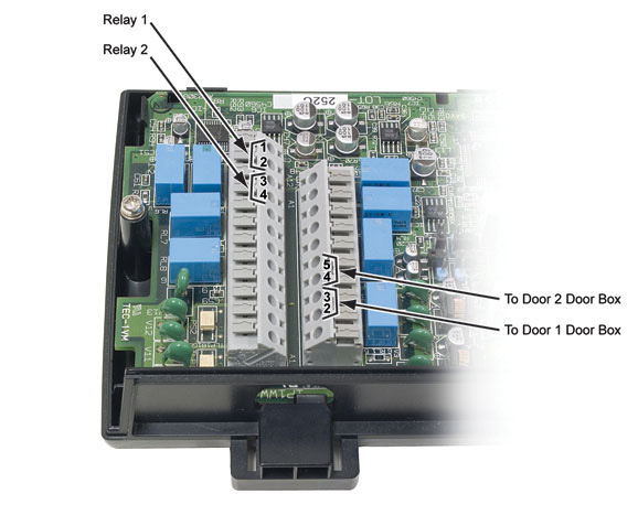
- Terminal 1 is at the bottom of the block.
- Terminals 2 and 3 are for Door Box 1. Be sure to skip terminal 1.
- Terminals 4 and 5 are for Door Box 2.
- The block on the left is the Relay Block.
- Terminal 1 is at the top of the block.
- Terminals 1 and 2 are for Relay 1.
- If you dial the extension number for Analog Door Box 1 and press [Open Door] [Open], Relay 1 will close.
- Terminals 3 and 4 are for Relay 2.
- If you dial the extension number for Analog Door Box 2 and press [Open Door] [Open], Relay 2 will close.
- The block on the right is the Door Box Block.
- The following drawing shows the completed wiring for both Analog Door Boxes with relay control.
Setting the 2PGDAD Module Jumpers
The jumpers to the right of the Connecting Blocks set the function of the 2PGDAD Module. When you are done wiring the 2PGDAD Module, be sure the jumpers are set correctly.
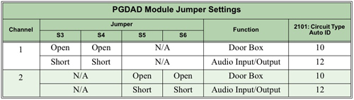
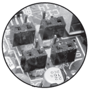
- Since you are setting up Door Boxes, be sure the jumpers are open. See
the illustration below.
- Do not connect the 2PGDAD to a 16ESIU port. You will do this after you program the 2PGDAD Module.
- Go to PGDAD Programming Basicsto assign the 2PGDAD Module primary and secondary ports.
- Go to Programming Analog Door Boxesfor additional Door Box programming.
- There is no programming required to assign or activate the 2PGDAD Module relays.